Contents:
Chapter 1: Introduction
Graphics Areas
Core areas:
- Modeling
- Rendering
- Animation
Other related ares: - User interaction - Virtual reality - Visualization - Image processing - 3D scanning - Computational photography
Major Applications
- Video Games
- Cartoons
- Visual Effects
- Animated Films
- CAD/CAM
- Simulation
- Medical Imaging
- Information visualization
Graphics API's
Need to deal with at least two different API's : Graphics API and a User Interface API
Graphics Pipeline
A special software/hardware subsystem that efficiently draws 3D primitives in perspective.
Usually optimized for processing triangles with shared vertices.
Basic operations map 3D vertex locations to 2D screen positions and shade the triangles so that they both look realistic and appear in proper back to front order.
Although drawing from back to front was once one of the most challenging research issues in Computer Graphics, now it is almost always solved by z-buffer.
It turns out that the geometric manipulation used in the graphics pipeline can be accomplished almost entirely in a 4D coordinate space composed of three traditional geometric coordinates and a fourth homogeneous coordinate that helps with perspective viewing. These 4D vectors are manipulated using 4 X 4 matrices and 4-vectors. The pipeline, therefore consists of machinery for effectively processing and composing such matrices and vectors.
This 4D coordinate system is certainly the biggest intellectual hurdle to jump when first learning computer graphics.
Numerical Issues
IEEE Floating point standards, allows programmer to make many convenient assumptions about numeric conditions to be handled.
Three special values: infinity, -infinity and NaN
Efficiency
There are no magic rules...
- Write the code in a straightforward way. Compute results on the fly.
- Compile in optimized code.
- Use profiling tools to find bottlenecks
- Examine data structures to look for ways to improve locality. If possible make data unit sizes match to cache/page size on the target architecture.
- If profiling reveals bottleneck in computations, examine the assembly code generated by the compiler. rewrite the source code to solve any problems.
Designing and Coding Graphics programs
Class Design, vector2, vector3, hvector, rgb, transform, image,
Float vs Double,
Debugging Graphics Programs,
The Scientific method, Look at the output, develop a hypothesis, test it, fix it.
Images as coded debugging output,
Data visualization for debugging
Chapter 2 : Miscellaneous Math
The cleaner the math, The cleaner the code.
Sets and Mappings
Mappings as in Functions.
Cartesian product, Common sets and notations such as real numbers, non-negative real numbers, ordered pairs in real 2D plane, points in n-dimensional Cartesian space, integers, the set of 3D points on the unit sphere.
Inverse mappings and bisections.
Intervals, open and closed,
set operations on intervals.
Logarithms.
Quadratic Equations
Trigonometry
Angles, Trigonometric functions, Pythagorean theorem, polar coordinates.
Useful identities, Shifting identities, Pythagorean identities, Addition and subtraction identities, half-angle identities, product indentions, Law of sines, cosines and tangents, area of triangle.
Vectors
A vector describes a length and a direction.
Vector operations, Cartesian coordinates.
Dot product, cross product.
Orthogonal bases and coordinate frames.
Curves and surfaces
2D Implicit curves, Gradient, derivatives.
Implicit lines, curves,
3D surfaces, surface normal, planes, 3D Quadric surfaces.
2D Parametric curves, 3D parametric curves
Linear interpolation
Triangles
Barycentric coordinates, 2D triangles, 3D triangles.
Chapter 3: Raster Images
Pixel : Picture element
Raster is just a 2D array of pixels.
Images can also be in vector format. Such images are resolution independent and are used where precession is important and photographic images and complex shading is not needed.
Raster Devices
- Output
- Display
- Transmissive: Liquid Crystal Display(LCD)
- Emissive : Light Emitting Diode (LED)
- Hardcopy
- Binary : Ink-jet
- Continuous tone : Dye sublimation printer
- Display
- Input
- 2D array sensor : digital camera
- iD array sensor : flatbed scanner
Displays
Emissive : Use pixels that directly emit controllable amounts of light.
Transmissive : Requires a light source to illuminate them. Generally a backlight in case of LCD, or a lamp in case of a projector.
Screen resolution.
Hardcopy Devices
Ink jet printer, thermal dye transfer, pixel density
Input Devices
Camera, Scanner
Images, Pixels and Geometry
Image as a function(mapping) from coordinate space to pixel value.
Pixel Values :
Pixel value ranges and different image formats like
- 1-bit grayscale : text and other images where intermediate grays are not desired (high resolution required);
- 8-bit RGB fixed-range color (24 bits total per pixel) : web and email applications, consumer photographs;
- 8- or 10-bit fixed-range RGB (24–30 bits/pixel) : digital interfaces to computer displays;
- 12- to 14-bit fixed-range RGB (36–42 bits/pixel) : raw camera images for professional photography;
- 16-bit fixed-range RGB (48 bits/pixel) : professional photography and printing; intermediate format for image processing of fixed-range images;
- 16-bit fixed-range grayscale (16 bits/pixel) : radiology and medical imaging;
- 16-bit “half-precision” floating-point RGB : HDR images; intermediate format for real-time rendering;
- 32-bit floating-point RGB : general-purpose intermediate format for software rendering and processing of HDR images.
Resulting artifacts,
- Clipping: When pixels that would otherwise be brighter than the maximum value set are clipped too the maximum value.
- Quantization/Banding:* When formats with fixed precession are used, it causes visible jumps in intensity or color.
Monitor intensities and Gamma
displayed intensity = (maximum intensity)\(\alpha_{\gamma}\),
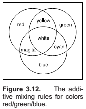
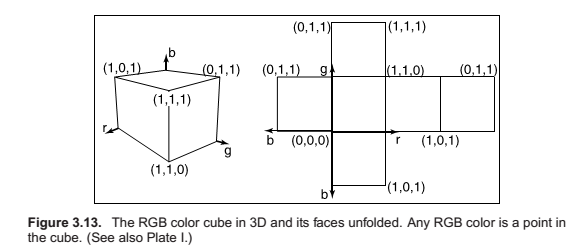
RGB Color
Alpha Compositing
Blending for partially covering pixels and transparent pixes.
Image Storage
lossless vs lossy formats.
- jpeg : lossy, compresses based on thresholds in human visual system. Works well for natural images.
- tiff : binary images, lossless compressed, 8 or 16 bit RGB
- ppm : lossless, uncompressed, 8-bit RGB,
- png : set of lossless formats, good set of open source management tools.
Chapter 4 : Ray Tracing
Rendering
rendering is a process that takes as its input a set of objects and produces as its output an array of pixels.
Image-order vs Object-order rendering.
Ray tracing is an image-order algorithm.
Basic ray tracing algorithm
A basic ray tracer has three parts:
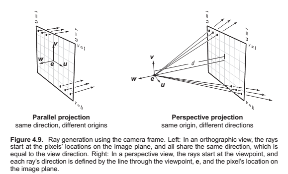
- ray generation, which computes the origin and direction of each pixel’s viewing ray based on the camera geometry;
- ray intersection, which finds the closest object intersecting the viewing ray;
- shading, which computes the pixel color based on the results of ray intersection.
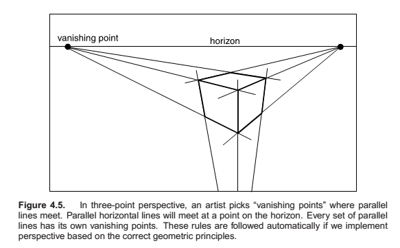
Perspective

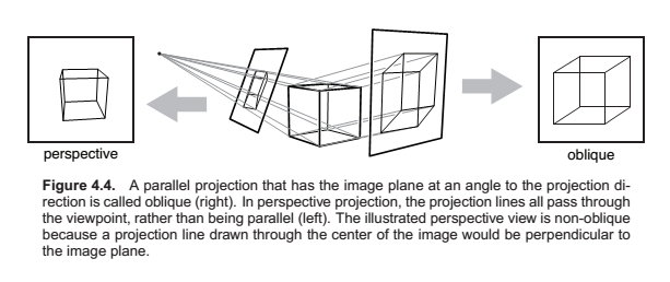
Computing Viewing Rays
The Viewpoint and the image plane.
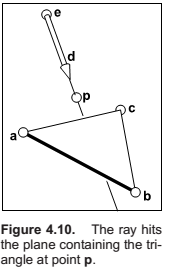
Ray Object Intersection
Ray-Sphere intersection:
Ray-triangle intersections: Using barycentric coordinates.
Ray-polygon intersection:
Ray-object intersection:
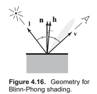
Shading
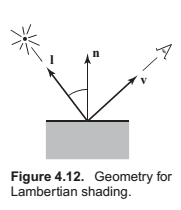
A shading model.
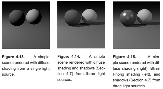
Lambertian Shading
Blinn-Phong shading
Lambertian shading is view independent. It does not have specular reflections that many surfaces have.
Ambient Shading
Multiple Point Lights
Superposition - the effect caused by more than one light source is simply the sum of the effects of the light sources individually.
A Ray tracing program
Object oriented design for a Ray-tracing program
Some discussion on Surface class, hit method, bounding box and Material class.
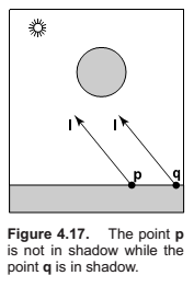
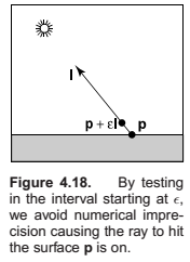
Shadows
Comments
comments powered by Disqus